1. The Unique Risks of Cracking in Medical Products
The hazards of cracking in medical injection-molded products far exceed those in ordinary industrial items:
-
Biocompatibility risks: Cracks may become breeding grounds for bacteria, increasing infection risks.
-
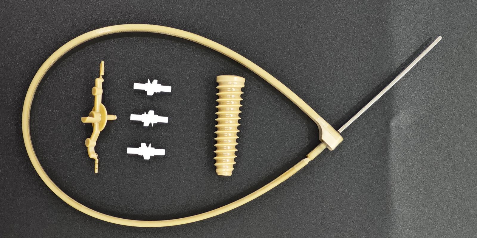
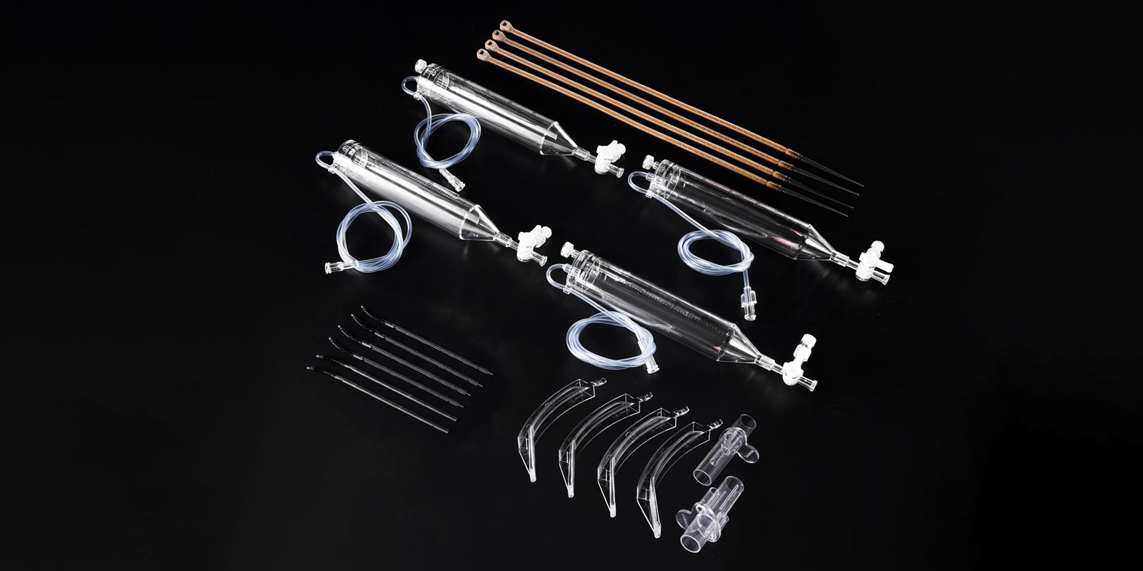
Functional failure risks: For example, cracking in syringe connectors can lead to liquid leakage.
-
Regulatory compliance risks: Certification systems like FDA and CE impose strict requirements on product integrity.
Case Study: A brand of disposable syringes experienced piston detachment due to cracking at the ejector pin area, triggering a mass recall. This underscores the critical importance of cracking control in medical products.
2. Material Selection and Pre-Treatment
2.1 Medical-Grade Material Adaptability
-
Priority choices: Polycarbonate (PC), Polyphenylsulfone (PPSU), and other chemically resistant materials.
-
Special requirements:
-
DEHP-free PVC requires special stabilizers.
-
Transparent components demand colorless, UV-resistant PC.
-
Recycled material restrictions: Medical products must use virgin medical-grade materials; recycled materials are prohibited.
2.2 Pre-Drying Process Optimization
-
Drying parameters:
-
PC: 120°C/4–6 hours (dew point ≤ -40°C).
-
PPSU: 150°C/8 hours (nitrogen protection required).
-
Equipment requirements: Use dehumidifying dryers with humidity monitoring to ensure moisture content ≤ 0.02%.
3. Key Control Points in Mold Design
3.1 Ejection System Optimization
-
Balanced ejection: Multi-point ejection with ejector pins ≥3mm in diameter and spacing ≤50mm.
-
Draft angles: Sidewall draft angles ≥3°, rib areas ≥5°.
-
Surface treatment: Cavity surfaces coated with hard chromium (HV ≥ 800) and polished to Ra ≤ 0.2μm.
3.2 Gating System Design
-
Gate selection:
-
Thin-walled parts (≤2mm): Submarine gates, 0.8–1.2mm in size.
-
Thick-walled parts (>2mm): Fan gates, width 1.5× wall thickness.
-
Runner optimization: Use hot runner systems with temperature control accuracy ±1°C.
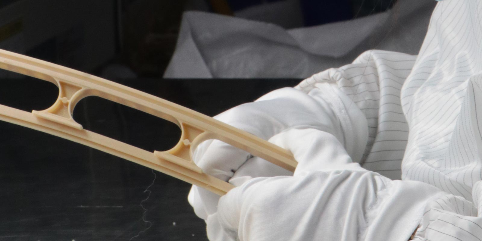
3.3 Structural Stress Design
-
Fillet transitions: All internal corners R ≥ 0.5mm, external corners R ≥ 0.3mm.
-
Rib design: Thickness ≤60% of main wall thickness, height ≤3× wall thickness.
-
Metal insert treatment: Preheat inserts to 120–150°C and apply nickel plating.

4. Precision Control of Molding Processes
4.1 Temperature Management
-
Barrel temperatures:
-
PC: 280–320°C (five-zone control).
-
PPSU: 340–380°C (requires dedicated high-temperature screw).
-
Mold temperatures:
-
Transparent parts: 80–100°C (oil temperature control).
-
Non-transparent parts: 60–80°C (water temperature control).
4.2 Pressure Curve Optimization
-
Injection pressure: Multi-stage control (example):
-
First stage: 80% max pressure (filling).
-
Second stage: 60% max pressure (packing).
-
Third stage: 40% max pressure (compensation).
-
Packing time: Set based on wall thickness (2–3 seconds per 1mm).
4.3 Speed Control Strategy
-
Injection speed: Slow-fast-slow three-stage control:
-
Initial stage: 10–20% max speed (prevents vortexing).
-
Middle stage: 80–90% max speed (filling).
-
Final stage: 30–40% max speed (prevents overfilling).
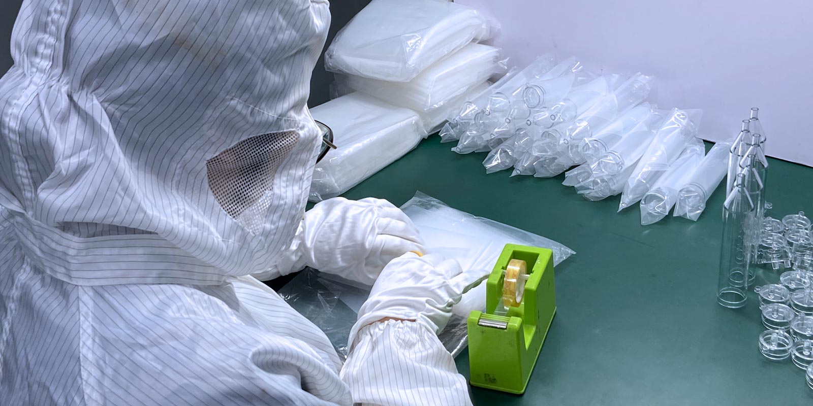
5. Environmental and Post-Processing Controls
5.1 Cleanroom Requirements
-
Temperature/humidity control: 23 ± 2°C, 45 ± 5% RH.
-
Cleanliness: ISO Class 7 (10,000) or higher.
-
Static control: Floor resistance 10⁶–10⁹Ω, personnel wear ESD garments.
5.2 Post-Processing Techniques
-
Annealing:
-
PC products: 110°C/2 hours (air circulation oven).
-
PPSU products: 180°C/4 hours (nitrogen protection required).
-
Surface treatment: Plasma treatment for critical contact surfaces to enhance surface energy.
6. Quality Inspection and Traceability
6.1 Online Inspection Systems
-
Visual inspection: High-resolution CCD cameras (resolution ≥ 0.02mm).
-
Stress detection: Polariscopes for residual stress distribution.
-
Dimensional inspection: Coordinate measuring machines (accuracy ±0.005mm).
6.2 Batch Traceability System
-
Material traceability: Each batch includes COA (Certificate of Analysis) and MSDS.
-
Process traceability: Record key parameters (temperature, pressure, time).
-
Product traceability: Laser marking or RFID chips for full lifecycle tracking.
7. Typical Case Studies
Case 1: Cracking in Syringe Connectors
-
Problem: Ring-shaped cracks after 6 months of storage.
-
Root causes:
-
Large CTE mismatch between aluminum insert (23×10⁻⁶/°C) and PC (65×10⁻⁶/°C).
-
Unpreheated inserts causing interface stress concentration.
-
Solutions:
-
Switch to PPSU (CTE 50×10⁻⁶/°C).
-
Preheat inserts to 150°C.
-
Add a 0.2mm silicone buffer layer.
Case 2: Cracking in Syringe Piston Ejector Areas
-
Problem: Whitening cracks at the ejector pin.
-
Root causes:
-
Insufficient draft angle (actual 2° vs. designed 3°).
-
Rough ejector pin surface (Ra 0.8μm, exceeding standard).
-
Solutions:
-
Increase draft angle to 3.5°.
-
Hard chrome-plate and polish ejector pins to Ra 0.2μm.
-
Reduce ejection speed from 150mm/s to 80mm/s.
8. Future Technological Directions
-
Smart injection systems: Integrate pressure, temperature, and stress sensors for real-time closed-loop control.
-
Nanocomposite materials: Develop self-healing nano-coatings.
-
Simulation optimization: Use CAE software to predict cracking risks.
-
3D-printed molds: Accelerate mold verification and shorten development cycles.
Conclusion: Cracking control in medical injection-molded products requires a holistic quality management system from material selection to post-processing. By implementing the proposed solutions, a medical enterprise reduced cracking rates from 3.2% to 0.15%, saving over $500,000 annually in quality losses. As reliability demands rise, refined and intelligent cracking control technologies will become core competitive advantages in the industry.


 Home
Home