

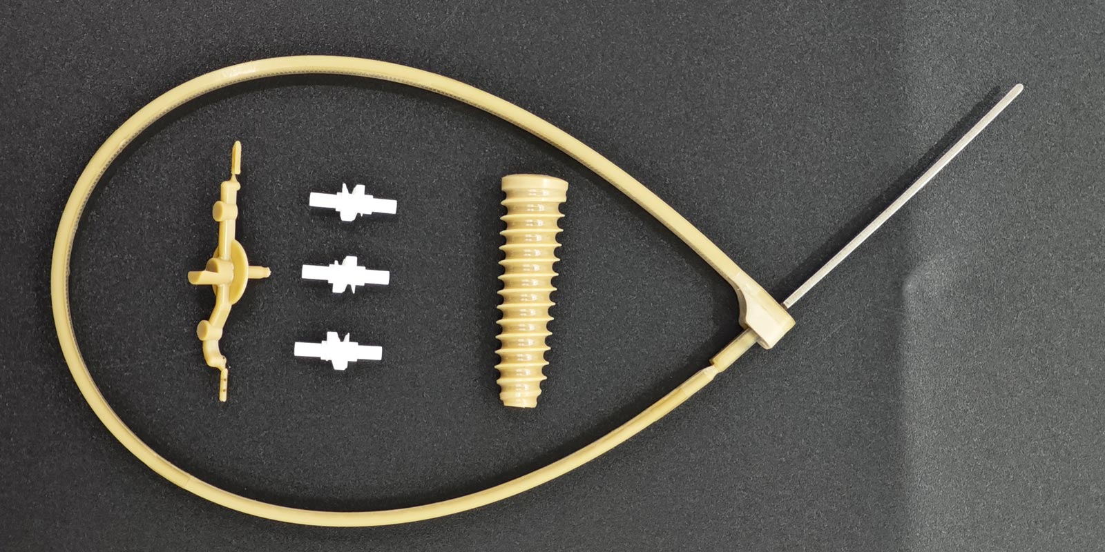
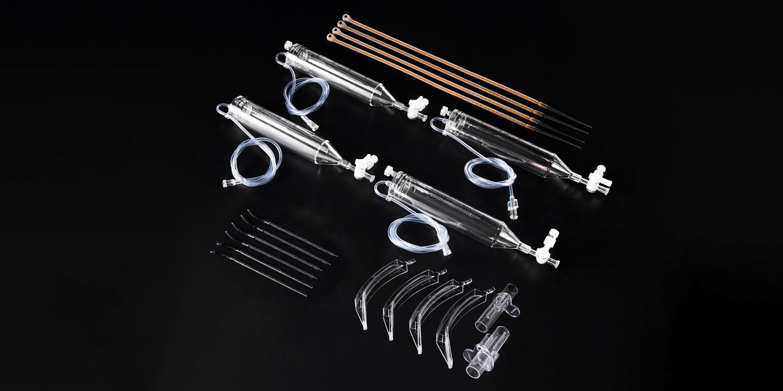


In the medical injection molding field, product surface quality is directly related to safety and compliance. Cold slug marks, as one of the most common surface defects in the gate area, not only ruin the appearance of the molded part but also become a fatal weakness in painting and plating processes. On high-cleanliness medical devices, they can even form stress concentration points and reduce part strength. For medical products that tolerate zero flaws, cold slug marks are by no means a minor issue. They are a red alert sent to the designer by the entire production system — process, mold, and material.
Rather than repeatedly adjusting machine settings after mass production starts, it is far better to address the root cause at the design source. The following systematically reviews cold slug mark improvement strategies from three dimensions: mold design, gating system, and material matching.
The formation mechanism of cold slug marks ultimately boils down to two paths:
Path 1: Front-end cold slug invasion. Cold material in the nozzle or runner (solidified due to machine stoppage, waiting, or runner heat dissipation) is pushed into the cavity along with the melt, forming foggy or bright marks near the gate. On thick-walled parts, it can even leave worm-like curved scars.
Path 2: Excessive packing pressure intrusion. When the packing time is too long or the pressure is too high, already-solidified cold material in the runner and gate area is forcibly squeezed into the part surface, forming small round bright spots close to the gate.
Regardless of which path is at play, if the design side does not take preventive measures, subsequent process adjustments will always be symptomatic treatment at best.
Medical products have extremely high requirements for precision and cleanliness. Mold design must intercept cold slugs outside the cavity.
First, cold slug wells must be fully and correctly designed. A cold slug well is not just a randomly drawn groove. Its volume must be precisely calculated based on the runner size and material fluidity to ensure it can trap the front-end cold material. For directly fed molds, the cold material in the nozzle must be cleared before mold closing, and the main runner residual cold material must be removed when the mold opens for part ejection. The depth of the cold slug well is generally recommended to be 1.5 to 2 times the runner diameter, and the width should be slightly larger than the runner.
Second, gate form, size, and position must be comprehensively considered. A gate that is too small causes the melt to pass at an extremely high shear rate, generating shear heat that triggers material degradation, while also causing poor venting and gas heating that scorches the plastic. It is recommended to appropriately enlarge the gate diameter, change sharp-corner gates to rounded transitions, and reduce the risk of melt fracture. The gate position should avoid dead-end areas where melt converges, to prevent cold material from accumulating there.
Third, mold venting must be unobstructed. Gas interference can cause turbid marks at the gate, which is especially fatal on high-gloss or plated surfaces of medical products. Sufficient venting slots, venting inserts, or ejector pin air-channeling devices should be set near the gate and at the melt end. The venting slot depth should be controlled between 0.02 and 0.05 millimeters, so that it can vent gas without producing flash.
Fourth, the matching dimensions between the nozzle and the mold feed entry must be precisely designed. The nozzle centering must be accurately adjusted. If the fit gap is too large, material leakage will form cold slugs; if it is too small, wear will accelerate. It is recommended to use self-locking nozzles or hot runner pin-point gates to eliminate nozzle cold slug problems at the root.

Medical injection molded parts often have uneven wall thickness and complex structures. The gating system design directly determines the flow state of the melt.
Balance the runner cross-section. If the runner is too small, the resistance is high, the melt stagnates and cools, and the front-end material temperature drops sharply. If the runner is too large, material is wasted and the cycle time increases. The runner diameter should be reasonably set according to the part weight and material fluidity. Typically, the main runner diameter is 6 to 12 millimeters, and the branch runner is 4 to 8 millimeters.
Adopt multi-stage injection strategies. For medical parts that are far from the gate or have large wall thickness variations, a single injection speed is difficult to handle. It is recommended to reserve a multi-stage injection process window during the mold design stage, adjusting the injection rate segment by segment so that the melt fills the cavity in laminar flow rather than turbulent flow, fundamentally eliminating front-end overcooling.
Gate position should preferentially be at the thick wall. Inserts and gates should be placed at the thick-wall areas of the part. On one hand, the mold temperature is higher at thick walls, making cold slug formation less likely. On the other hand, it helps reduce orientation stress and lowers the risk of deformation caused by internal stress.
Design is not just about the mold. Material selection is equally critical.
Thorough drying is the baseline. Medical-grade plastics such as PC, ABS, and PP must be strictly dried. Water vaporization creates bubbles and destroys interlayer bonding, indirectly worsening cold slug marks. It is recommended to set drying temperature and time according to material characteristics. ABS generally requires drying at 80 degrees Celsius for 2 to 4 hours, while PC requires drying at 120 degrees Celsius for 4 to 6 hours.
Use fewer lubricants to prevent powder contamination. Excessive lubricants reduce the friction coefficient between materials, causing melt flow to become uncontrollable, and cold material is more easily swept into the cavity.
Screw and barrel matching cannot be ignored. If the screw has worn dead spots or the heating system is out of control, the plastic will undergo long-term thermal decomposition, producing high-viscosity melt and carbonized substances. These carbonized materials enter the cavity along with the melt and form black spots that look very similar to cold slug marks. At the design stage, wear-resistant screw assemblies should be selected, and the fit gap between the check ring and thrust ring should be inspected regularly.
Medical product development cycles are long and mold trial costs are high. It is strongly recommended to perform mold flow analysis (Moldflow) before mold making. By simulating the filling process, you can predict in advance the weld line positions, filling pressure distribution, shear heat concentration areas, and poor venting locations. Although mold flow analysis cannot completely replace mold trials, it is sufficient to identify most hard faults and kill the risk of cold slug marks at the design stage. This upfront investment is far cheaper than later mold modifications.
Q: How do you distinguish between cold slug marks and burn marks?
A: Cold slug marks appear foggy or bright, mostly in a cloud-like or worm-like pattern near the gate. Burn marks appear yellowish-brown or black, accompanied by a charred smell. Cold slug marks result from insufficient temperature, while burn marks result from excessive temperature. The two have opposite causes and require completely different handling approaches.
Q: Can raising the mold temperature completely solve cold slug marks?
A: Raising the mold temperature is one of the most direct and effective methods. It can significantly slow down the cooling speed of the front-end material. However, if the cold slug well is undersized or packing pressure is excessive, simply raising the temperature cannot cure the problem. Mold structure optimization must be combined.
Q: How strict is the tolerance for cold slug marks on medical products?
A: Medical devices, especially Class III implants and in vitro diagnostic equipment, cold slug marks not only affect appearance but can also become stress concentration points and micro-environments for bacterial growth. Most standards require no visible surface defects. Therefore, the design stage must adopt zero tolerance, and post-processing to cover up defects is not acceptable.
PREV:Why Do Medical Injection-Molded Parts Keep Failing? A Comprehensive Guide
NEXT:How to Optimize Weld Lines on Medical Injection Molded Parts?
Add: 62 Jinghai East Road, Chang'an Town, Dongguan City, Guangdong Province
Whatsapp: +86 13342659272
Email: Yuliya.chen@yizemould.com
Add: 62 Jinghai East Road, Chang'an Town, Dongguan City, Guangdong Province
Whatsapp: +86 13342659272
Email: Yuliya.chen@yizemould.com
 Home
Home